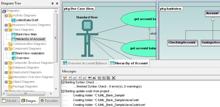
25+ component diagram in software engineering
The named Automation is a placeholder for a nested state diagram. Component diagrams are often drawn to help.

How Do We Innovate The Component Industry From What It Already Is Can We Passive House Passive House Design Passive Solar Design
For example include Order processing.

. INTRODUCTION UML component diagrams describe software components and their dependencies to each others A component is an autonomous unit within a system The. Software Ideas Modeler allows you to utilize its toolset to bring engineering methods to your software development. UML is a diagramming language created for software developers to visualize construct and document aspects of software.
Components of an ER Diagrams 1. Action-expression- description bod computation. UML Component diagrams are used in modeling the physical aspects of object-oriented systems that are used for visualizing specifying and documenting component-based systems and also.
An entity can be a real-world object either animate or inanimate that can be merely identifiable. Up to 24 cash back Pre-drawn UML component diagram symbols represent component package package container dependency generalization tranparent stereotype. A component diagram shows the internal parts connectors and ports that implement a component.
UML typically has graphic elements that. Component-Based Software Engineering CBSE is a process that focuses on the design and development of computer-based systems with the use of reusable. - Display the structural relationship of software systems and their elements.
A Data Flow Diagram DFD is a traditional visual representation of the information flows within a system. The DE will connect to the development stage be it Visual Basic Java C and so on. A neat and clear DFD can depict the right amount of the system requirement.
This software component diagram template can help you. This will speak with the CMP while the development is occurring taking a gander at the. You can use various.
Uses of State Diagram. A component diagram also known as a UML component diagram describes the organization and wiring of the physical components in a system. A profile diagram is any diagram which is created in a package.
Uses of State Diagram. UML Profile Diagram in Software Engineering. An entity is denoted as a rectangle in an ER diagram.
When the component is instantiated copies of its internal parts are also. Component diagrams are often drawn to help. For example include Order.
Diagrams for Software Development. Profile provide a means of extending the UML. - Simplify interactions within complex systems.
0-level DFD provides a brief overview of the software requirements as a single.
Altova Umodel Professional Edition

Top 25 Computer Architecture Interview Questions And Answers

I Made A Disassembly Schematic For The Iphone 6 Infos In Comments Iphone Apple Iphone Repair Iphone Solution Mobile Phone Repair
1
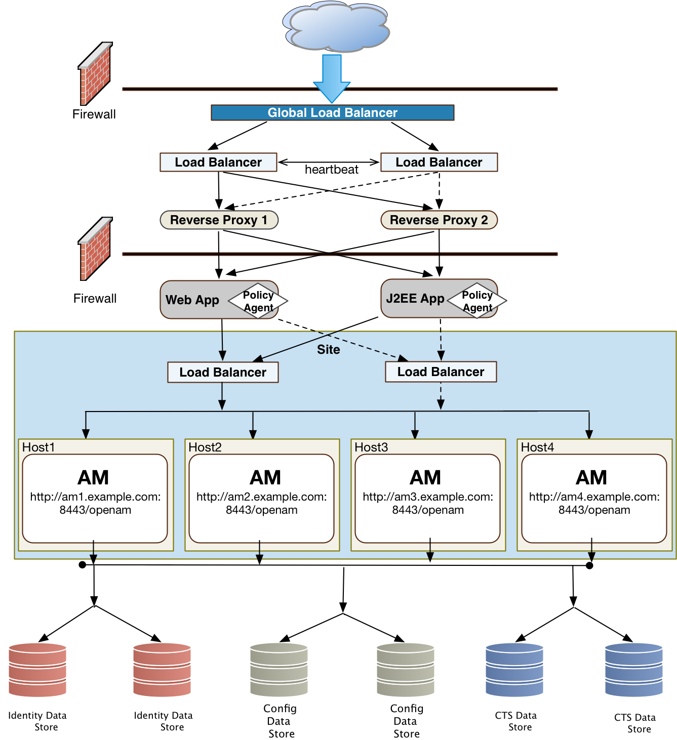
Am 6 Deployment Planning Guide

System Architecture Done Right Towards Data Science

Aws Architecture Diagram Template Mural

15 Awesome Css Flowchart Examples Onaircode Flow Chart Software Development Life Cycle Workflow Diagram
.webp)
Simple Architecture Diagram Uml Template Mural
Iphone 8 Plus Parts Diagram
1
15 Awesome Css Flowchart Examples Onaircode Flow Chart Software Development Life Cycle Workflow Diagram

Pin On Esp8266
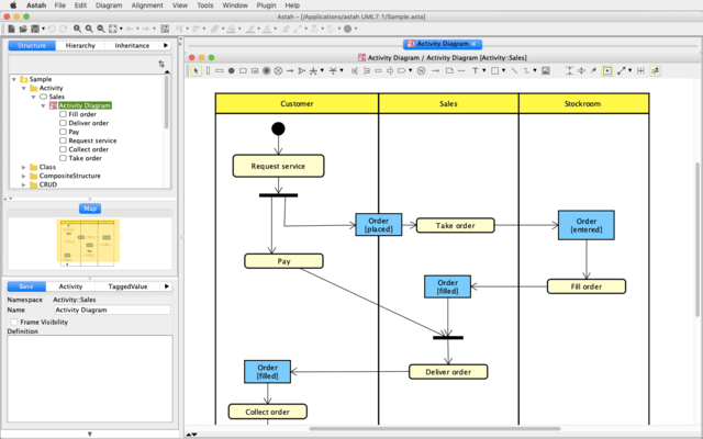
Astah Uml
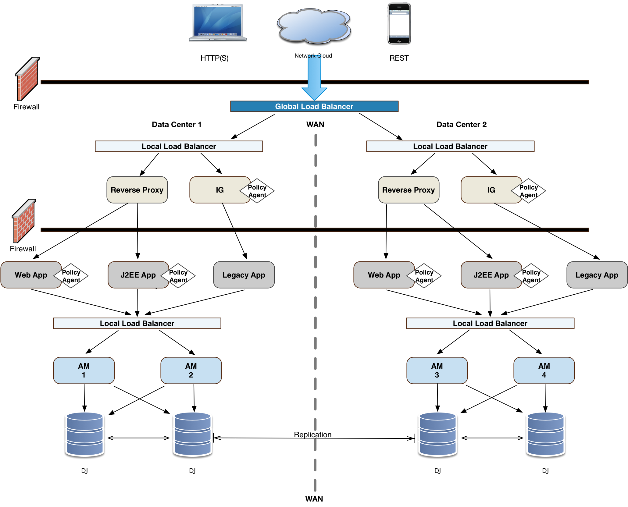
Am 6 Deployment Planning Guide

React Tree View Component Examples With Code Onaircode Coding Binary Tree Tree Structure
1